Table of Contents
Introduction
VLAN on pfSense, In today’s guide, we will see how to segregate our home network by creating VLAN on pfSense. This may be useful for someone who looks to set up a home lab with different subnets, Or to segregate IoT devices from unauthorized access.
I have a pfSense router and a Cisco SG300-10 Small business Management Switch for my home lab. Let me split my network into 4 for my lab setup from VLAN 10 to 40.
- VLAN 10 for a few management-related virtual servers.
- VLAN 20 for Kubernetes servers.
- VLAN 30 for OpenShift servers.
- VLAN 40 for anything related to the Security playground.
Documented for self reference in future to reconfigure the same.
Creating VLAN on the Switch side
I have a Layer 3 switch and I need to use VLAN, Creating VLAN is possible is the switch itself, However, I need to set up the VLAN on the pfSense side to get more feature from it. So, it necessary to configure both the switch and pfSense to have a working VLAN.
Let’s start to create the VLAN by login to the Switch.

Create a new VLAN by navigating to
VLAN Management –> VLAN Settings –> Add
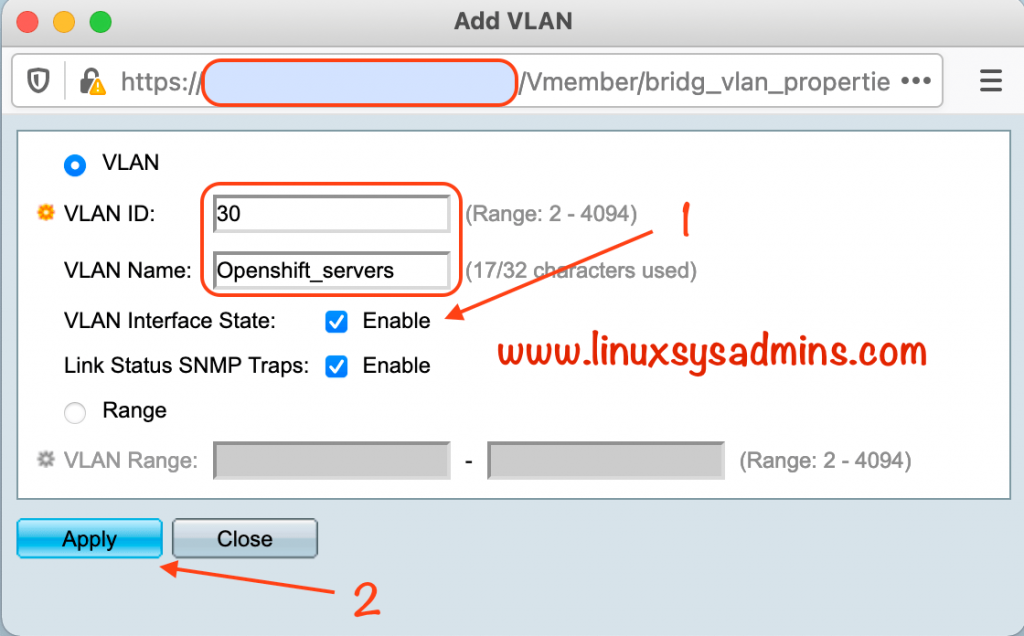
VLAN ID: 30
VLAN Name: Openshift_servers
VLAN Interface State: Enable
Link Status SNMP Traps: Enable
Click apply to create the VLAN
- Enable the interface state.
- Click apply to save the changes.
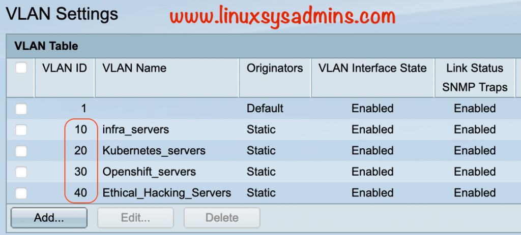
Finally, these are the list of created VLANs.
Changing Mode for Interfaces
Once the VLAN created we need to change the modes for each interface. Navigate to
VLAN Management –> Interface Settings
Select the port which required to change the mode and click edit. Now we should get a pop-up windows as shown below.
The mode I’m about to select is Trunk, In trunk mode the selected port can be member of one or more VLANs.
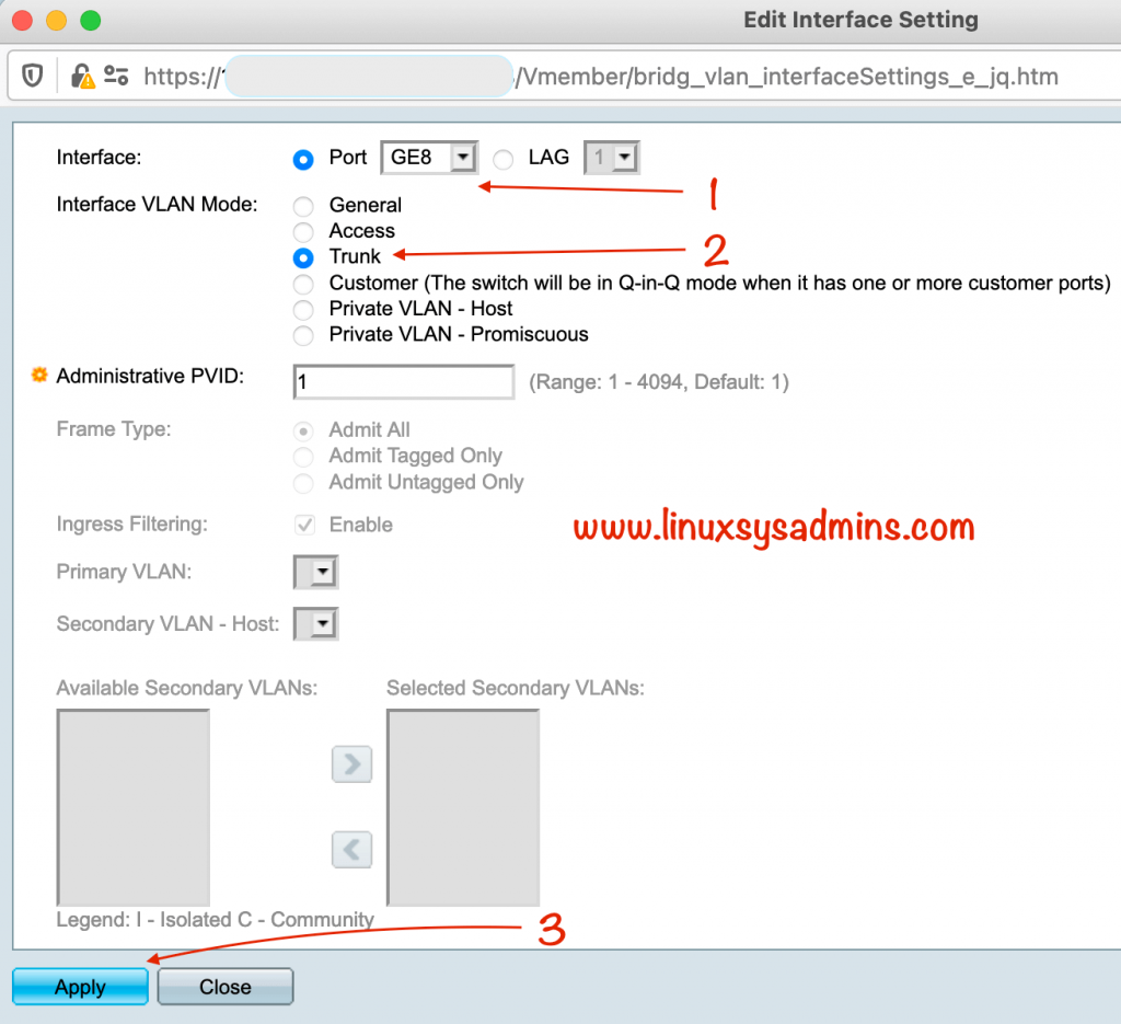
- Interface – Select the Interface.
- Interface VLAN Mode – Select the mode as the trunk.
- Click apply to make the changes.
Changing modes for the remaining interfaces can be easy if we plan to use only one mode. In my case, I’m planned to use only one mode which is the trunk. Click the Copy Settings to apply the same mode for the remaining ports. A pop-up window will be opened, provide the range (2-7) of the interface which is supposed to configure with the trunk mode.
I need to use port 6 and 7 in access mode, so I’ll reconfigure it later. For now, lets continue in trunk mode.
Finally, we have done the required interface settings for each port as a trunk.
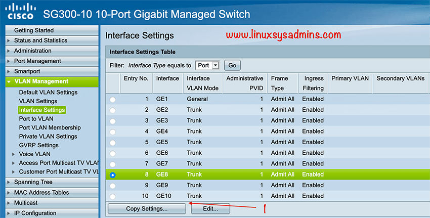
The above setting can be configured in other ways too using Port to VLAN. However, with limited options.
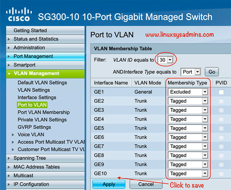
VLAN Management –> Port to VLAN
- Select the VLAN ID from the drop-down list and click GO
- Change the membership type as Tagged and click Apply
Verify Port to VLAN Membership
To Verify the VLAN port membership navigate to
VLAN Management –> Port VLAN Membership
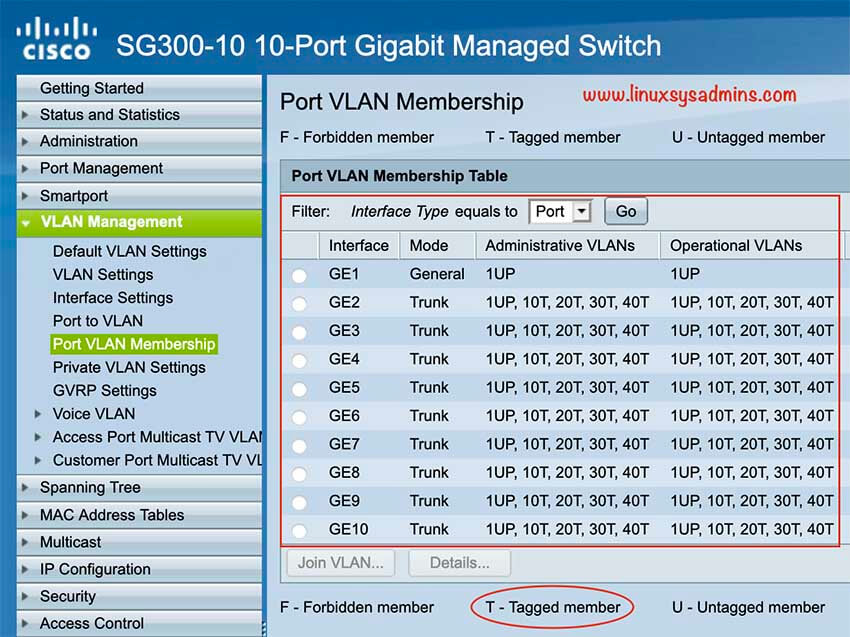
Here we should see the Operational VLANs for each port as “T” which represent Tagged. Don’t use DHCP on the switch side, To use the DHCP we will configure it from the pfSense.
That’s are the required changes in Switch side.
Setup VLAN on pfSense side
Create the VLAN in pfSense
Right after completing with configuring VLAN on switch side, let’s start to setup the VLAN in pfSense. To create the VLAN navigate to
Interfaces –> Interface Assignments –> VLANs
Click add to add a new VLAN.
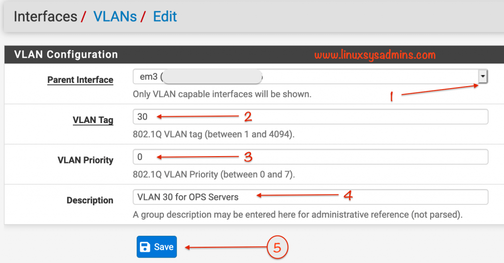
To set up the VLAN on pfSense, select anyone of the port from pfSense box and connect the cable to your switch. In my case, I’m about to use OPT2 port from pfSense.
- Parent Interface select em3 which is OPT2
- VLAN Tag enter the VLAN ID as 30
- VLAN Priority as 0
- Description Just a few words for future reference
- Click Save to make the changes persistent
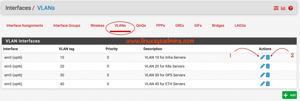
Finally, all the required VLANs are created in a single interface em3
- If you need to make any changes click the pencil icon to do the same.
- Using the Bin icon we can delete a VLAN at any time.
Interface Assignments
Once the VLAN created navigate to Interface –> Interface Assignment to assign the created VLANs.
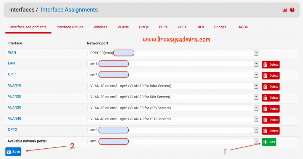
Click save to make the changes.
Creating Aliases for Firewall
After creating the interface and assignment we can’t reach other networks, to make it work we need to add a few firewall rules.
In some place, Instead of creating firewall rules for each network/hosts, we can create an alias and add the required network ranges. This will easy the firewall exclusion process in upcoming steps.
To create a IP Aliases for firewall rules, navigate to
Firewall –> Aliases –> Add
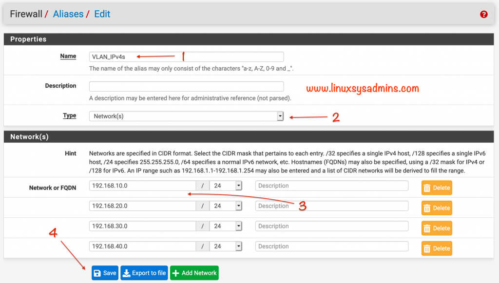
- Name – Give a name for our aliases
- Type – The type of alias to create. In our case, a network range.
- Network or FQDN – The network range and select the mask from the drop-down list.
- Save – Click to Save the changes.

A created alias will look like above.
Creating Firewall rules
Now let’s create the firewall rules to reach the networks each other, and to reach the internet.
To create the rules, navigate to
Firewall –> Rules –> VLAN30 –> Add
Here we need to create three firewall rules.
- The first rule is to allow the traffics within the subnet.
- The second rule is to allow the internet on VLAN30
- The final rule is to allow traffic between my LAN network from VLAN30.
Allow traffic within the Subnet
To allow the traffic within the subnet select both source and destination as VLAN30 net
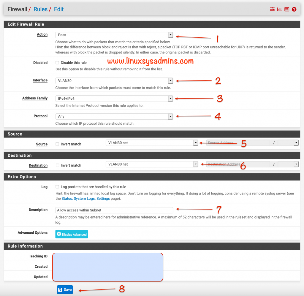
- Action – To “Pass” the traffic
- Interface – Select the “VLAN30″ from the drop-down list
- Address Family – Select the type, I’m using both “IPv4 + IPv6“
- Protocol – Select “Any” from the list
- Source – The source “VLAN30 net” from where you need to reach somewhere
- Destination – The actual Destination “VLAN30 net” where you need to reach
- Description – A small description for future reference
- Click Save to make the changes persistent
Allow Internet for VLAN30
Similar to above rule allow the internet for VLAN30.
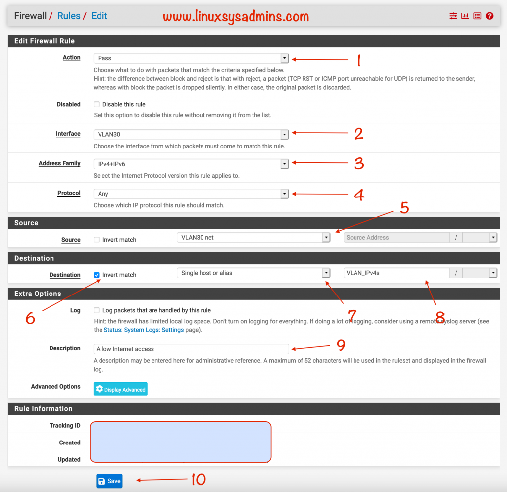
- Action – To “Pass” the traffic
- Interface – Select the “VLAN30″ from the drop-down list
- Address Family – Select the type, I’m using both “IPv4 + IPv6“
- Protocol – Select “Any” from the list
- Source – The source “VLAN30 net” from where you need to reach somewhere
- Destination – Check the “Invert match”
- And select “Single host or alias” from the list
- Type the alias name “VLAN_IPv4s“.
- Description – A small description for future reference
- Click Save to make the changes persistent
This will allow the internet for VLAN30.
Allow traffic between LAN to VLAN30
I need to reach the VLAN30 from my desktop, so adding a rule for the same.
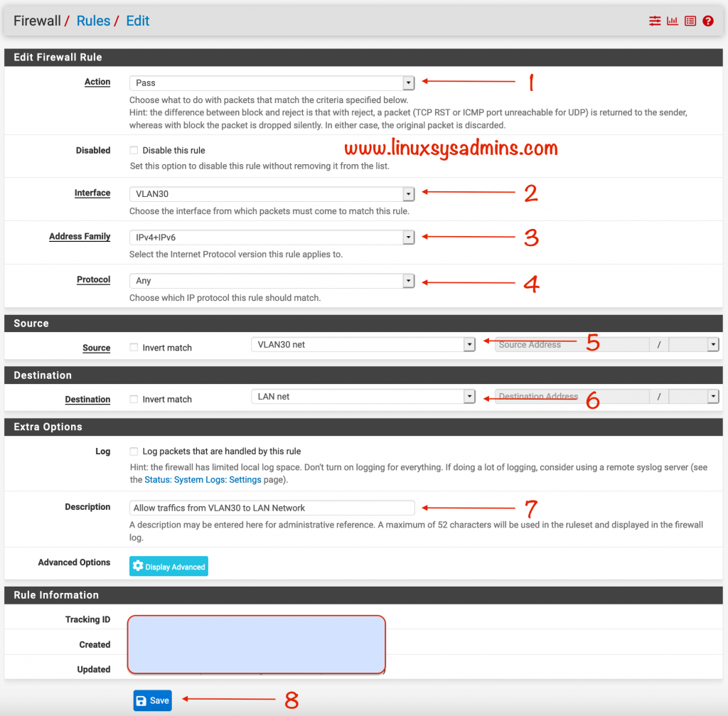
- Action – To “Pass” the traffic
- Interface – Select the “VLAN30″ from the drop-down list
- Address Family – Select the type, I’m using both “IPv4 + IPv6“
- Protocol – Select “Any” from the list
- Source – The source “VLAN30 net” from where you need to reach somewhere
- Destination – The actual Destination “LAN net” where you need to reach
- Description – A small description for future reference
- Click Save to make the changes persistent
Finally, these are the rules we have created.

If we need to delete a rule or in case if its not required any more
- check the box
- Click Delete to remove the rules for VLAN30.
To make the changes to any rules, click the pencil icon to do the same.
Configure Gateway for VLAN30
We need to add a route for VLAN 30 to reach the LAN network. To create the same, navigate to
System –> Routing –> Gateways –> Add
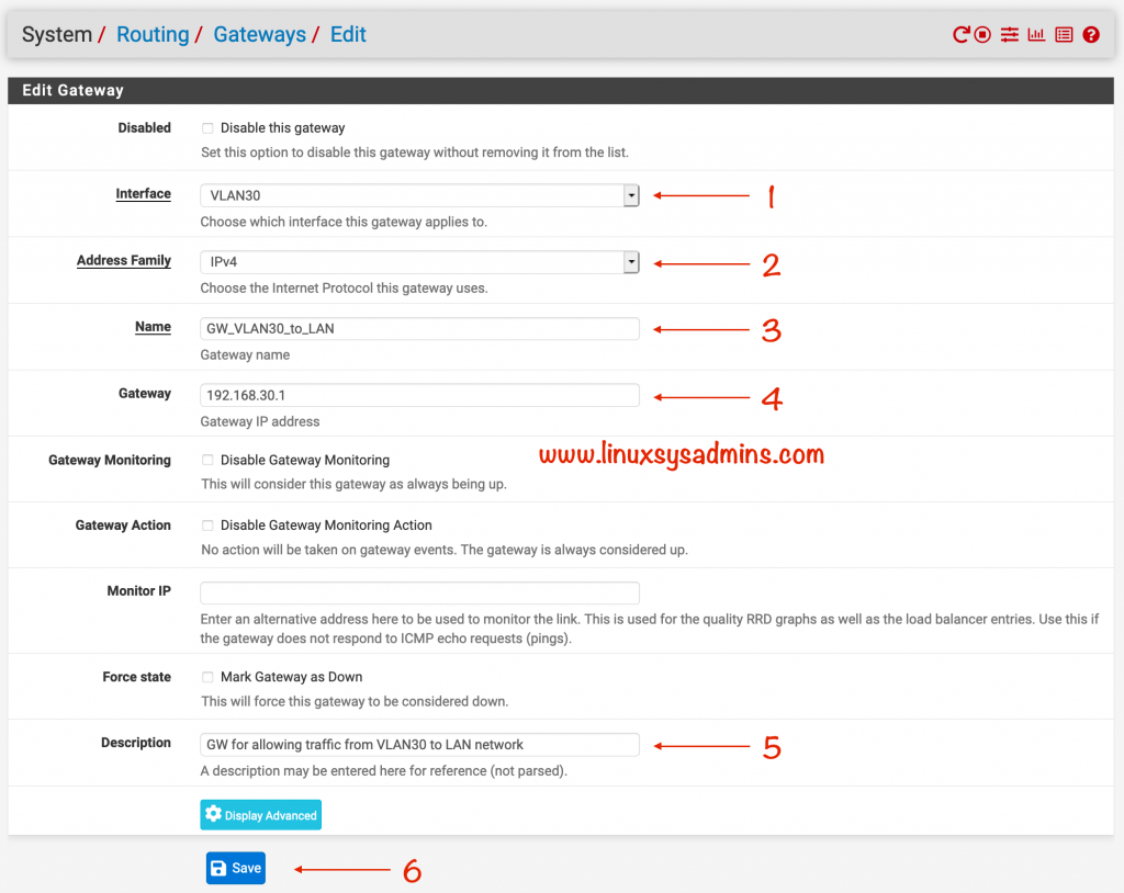
- Interface – Select the interface where you need to create the gateway
- Address Family – Now we are creating a route for only IPv4
- Name – A name for the route
- Gateway – The Gateway IP
- Description – A small description for future reference
- Click Save to make the changes
Configure DHCP for VLAN 30
In our previous switch configuration we have disabled the DHCP, Now let’s configure the DHCP for VLAN on pfSense side.
To enable the DHCP for VLAN 30, Navigate to
Services –> DHCP Server –> VLAN30
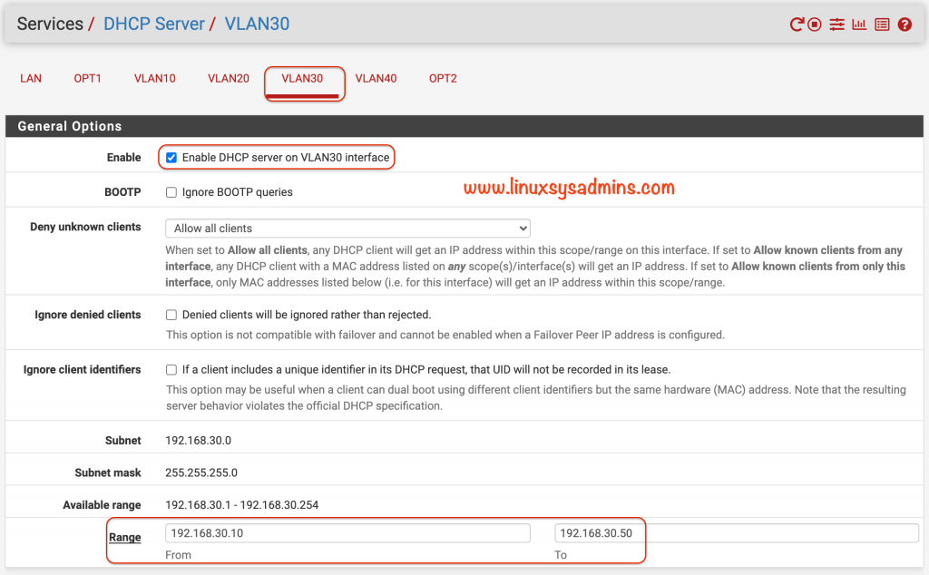
- Check the options Enable DHCP server for VLAN30 interface
- Create a DHCP pool for VLAN30, 40 numbers of IP is more than enough for my home lab.
Additionally, we can add DNS entries which need to be used on the clients side.

I have three numbers of DNS servers. I’m about to use all the three IPs to be configured in the client side.
Static IP Mapping for Cisco switch in pfSense
We need to configure a static IP for the Cisco switch on the pfSense side using its MAC. To do the same, we need to get the Base MAC Address of Cisco Switch.
Login to Cisco SG300-10 and Navigate to
Status and Statistics –> System Summary –> Base MAC Address: XX:XX:XX:XX:XX:XX
The Cisco switch was connected to the OPT2 port, So now we need to configure the static mapping for this interface under the OPT2.
Make sure to use a IP out of DHCP pool range.
Services –> DHCP Server –> OPT2
Scroll to the bottom of the page and click Add
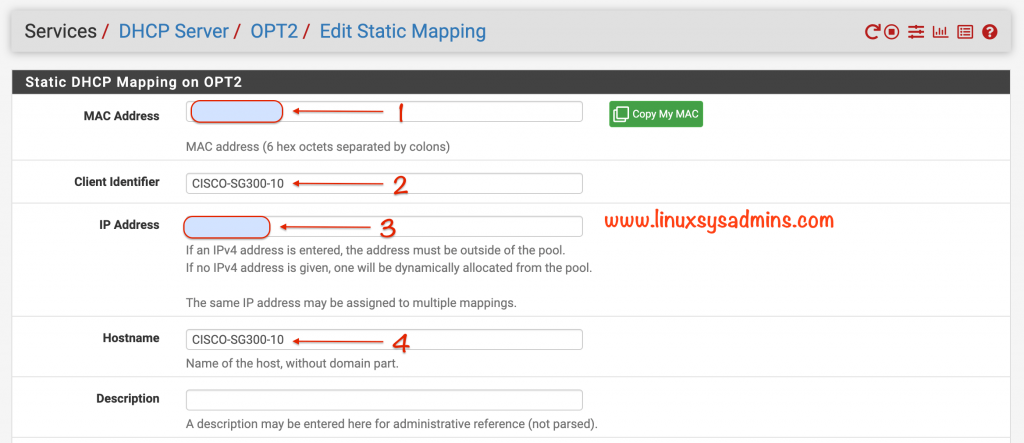
- Base Mac address copied from the Cisco switch
- A name to identify your switch in pfSense
- A static IP address for the Cisco switch in pfSense, The IP should not be part of the DHCP pool
- The name and the Client Identifier are the same.
- Scroll to the bottom and click Save.
Selecting an IP for static mapping out of DHCP pool is very important to have a stable VLAN on pfSense configuration.

The created DHCP static mapping will be listed at the bottom of the page.
Lets test the new VLAN on pfSense
Right after all the configs are done, it’s time to test the VLAN.
Launched a VM from the template, made the necessary changes to the interface with VLAN ID.
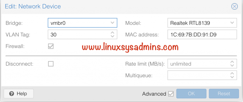
And below is the output for our VLAN on pfSense setup.
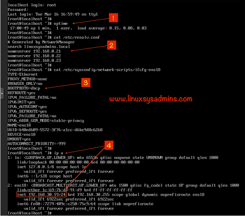
- Uptime of the new Virtual Machine
- Automatically configured DNS server entries.
- We are getting the IP from pfSense DHCP as we are using BootProto as DHCP.
- Print the IP address and here we can see a dynamically assigned IP address.
That’s it, we have successfully configured the Cisco SBM and pfSense to setup the VLAN on pfSense.
Conclusion
Creating a VLAN on pfSense just take few steps. However, if we use an additional L3 switch we need to make a few more changes to make it work. Subscribe to our newsletter for more how-to-guides on the pfSense. If you found this guide helpful, provide your feedback in below comment section.
Do you have an example of “Router On A Stick” configuration with pFSense?
Instead of having the pFSense doing all the routing to the subnets.
Using a Core Switch do to all the subnet routing then trunk a single port to the pFSense.
Hi,
If the VLAN port (EM2, OPT2) is connected to the switch, what happens with the LAN port (EM1)? Is EM1 left empty or disconnected?
During the setup time temporarily it was configured to use 192.168.1.x network for WIFI devices.
Do you need a switch? I have a 4-nic box (no wifi card) with pfsense and a asus wireless router converted to AP mode. 1) can I have 2 fully featured vlans? 2) Do you believe it is possible to have multiple vlans going to the asus AP?
Hi,
You don’t need a VLAN compatible switch if you don’t have a plan to use PORT mapping. No, I don’t think so multiple VLANs going to the Asus AP will work.
What do you need the rule ‘access within subnet’ for? Within the same subnet traffic will never be handeled by the firewall.